

|
|
||||||||
|---|---|---|---|---|---|---|---|---|
| Model |
|
|
|
|
|
|
|
|
| Phase |
|
|
||||||
| Max. Capacity (VA) |
|
|
|
|
|
|
|
|
| Max. Capacity (Watts) |
|
|
|
|
|
|
|
|
| Power Module Capacity |
|
|
||||||
| Max. Power Module No. |
|
|
|
|
|
|
|
|
| Grid System |
|
|||||||
| Voltage |
|
|||||||
| Voltage Range |
Others : 228V~304Vac (line-line) load decreases linearly according to the min phase voltage |
|||||||
| Frequency |
|
|||||||
| Frequency Range |
|
|||||||
| Power Factor |
|
|||||||
| Current THDi |
|
|||||||
| Dual Input |
|
|
||||||
| Inverter Voltage |
|
|||||||
| Inverter Frequency |
|
|||||||
| Output Power Factor |
|
|||||||
| Voltage Regulation |
|
|||||||
| Frequency Precision |
|
|||||||
| Crest factor |
|
|||||||
| Output THDu |
|
|||||||
|
|
||||||||
| Inverter Overload |
|
|
||||||
| Battery Voltage |
|
|||||||
| Charger Voltage precision |
|
|||||||
| Charger Power |
|
|||||||
| Cold Start Function |
|
|
||||||
| Voltage |
|
|||||||
| Voltage Range |
|
|||||||
| Frequency |
|
|||||||
| Frequency Range |
|
|||||||
| Bypass Overload |
125% to 130% for 10min 130% to 150% for 1min >150% for 300ms |
110% to 130% for 5min 130% to 150% for 1min >150% for 300ms |
|
|||||
| Normal Operation |
|
|||||||
| ECO Mode |
|
|||||||
| Battery Operation |
|
|
||||||
| Operation |
|
|||||||
| Storage |
|
|||||||
| Relative Humidity |
|
|||||||
| Noise |
|
|||||||
| Altitude |
|
|
||||||
| Dimension (W x D x H) (mm) |
|
|
|
|
|
|
|
|
| Cabinet Weight (kg) |
|
|
|
|
|
|
|
|
| Power Module Dimension |
|
|
||||||
| Power Module Weight |
|
|
|
|||||
| Display |
|
|||||||
| Interface |
|
|||||||
|
|
||||||||
| Other Function |
|
|||||||
|
|
|||||||
|---|---|---|---|---|---|---|---|
| Model |
|
(with PDU) |
|
|
|
|
|
| Phase |
|
|
|||||
| Max. Capacity (VA) |
|
|
|
|
|
||
| Max. Capacity (W) |
|
|
|
|
|
||
| Power Module Capacity |
|
|
|||||
| Max. Power Module No. |
|
|
|
|
|
|
|
| Grid System |
|
||||||
| Voltage |
|
||||||
| Voltage Range |
Others : 228V~304Vac (line-line) load decreases linearly according to the min phase voltage |
||||||
| Frequency |
|
||||||
| Frequency Range |
|
||||||
| Power Factor |
|
||||||
| Current THDi |
|
||||||
| Dual Input |
|
|
|
|
|||
| Inverter Voltage |
|
||||||
| Inverter Frequency |
|
||||||
| Power Factor |
|
||||||
| Voltage Regulation |
|
|
|||||
| Frequency Precision |
|
||||||
| Crest factor |
|
||||||
| Output THDu |
|
||||||
|
|
|||||||
| Inverter Overload |
|
|
|||||
| Battery Voltage |
|
||||||
| Charger Voltage precision |
|
||||||
| Charger Power |
|
||||||
| Cold Start Function |
|
|
|||||
| Voltage |
|
||||||
| Voltage Range |
|
||||||
| Frequency |
|
||||||
| Frequency Range |
|
||||||
| Bypass Overload |
110% to 125% for 10min 125% to 150% for 1min >150% for 200ms |
110% to 125% for 5min 125% to 150% for 1min >150% for 200ms |
|
||||
| Normal Operation |
|
|
|||||
| ECO Mode |
|
|
|||||
| Battery Operation |
|
|
|
||||
| Operation |
|
||||||
| Storage |
|
||||||
| Relative Humidity |
|
||||||
| Noise |
|
|
|||||
| Altitude |
|
|
|||||
| Dimension(mm) |
|
|
|
|
|
|
|
| Cabinet Weight (kg) |
|
|
|
|
|
|
|
| Power Module Dimension |
|
|
|||||
| Power Module Weight |
|
|
|
||||
| Display |
|
|
|||||
| Interface |
|
|
|||||
|
|
|
||||||
| Other Function |
|
|
|||||
|
|
|||||||||
|---|---|---|---|---|---|---|---|---|---|
| Model |
080M/40 |
160M/40 |
240M/40 |
400M/40 |
100M/50 |
200M/50 |
300M/50 |
500M/50 |
|
| Phase |
|
|
|||||||
| Max. Capacity (VA) |
|
|
|
|
|
|
|
|
|
| Max. Capacity (W) |
|
|
|
|
|
|
|
|
|
| Power Module Capacity |
|
|
|||||||
| Max. Power Module No. |
|
|
|
|
|
|
|
|
|
| Grid System |
|
||||||||
| Voltage |
|
||||||||
| Voltage Range |
Others : 228V~304Vac (line-line) load decreases linearly according to the min phase voltage |
||||||||
| Frequency |
|
||||||||
| Frequency Range |
|
||||||||
| Power Factor |
|
||||||||
| Current THDi |
|
||||||||
| Dual Input |
|
|
|
|
|
|
|
||
| Inverter Voltage |
|
||||||||
| Inverter Frequency |
|
||||||||
| Power Factor |
|
||||||||
| Voltage Regulation |
|
||||||||
| Frequency Precision |
|
||||||||
| Crest factor |
|
||||||||
| Output THDu |
|
||||||||
|
|
|||||||||
| Inverter Overload |
|
|
|||||||
| Battery Voltage |
|
||||||||
| Charger Voltage precision |
|
||||||||
| Charger Power |
|
||||||||
| Cold Start Function |
|
||||||||
| Battery Number |
|
|
|||||||
| Voltage |
|
||||||||
| Voltage Range |
|
||||||||
| Frequency |
|
||||||||
| Frequency Range |
|
||||||||
| Bypass Overload |
125% to 130% for 10min 130% to 150% for 1min >150% for 300ms |
110% to 125% for 5min 125% to 150% for 1min >150% for 1s |
125% to 130% for 10min 130% to 150% for 1min >150% for 300ms |
110% to 130% for 5min 130% to 150% for 1min >150% for 1s |
|
||||
| Normal Operation |
|
||||||||
| ECO Mode |
|
||||||||
| Battery Operation |
|
|
|||||||
| Operation |
|
||||||||
| Storage |
|
||||||||
| Relative Humidity |
|
||||||||
| Noise |
|
||||||||
| Altitude |
|
|
|||||||
| Dimension (W x D x H) (mm) |
|
|
|
|
|
|
|
|
|
| Cabinet Weight (kg) |
|
|
|
|
|
|
|
|
|
| Power Module Dimension (W x D x H) (mm) |
|
|
|||||||
| Power Module Weight |
|
|
|||||||
| Display |
|
||||||||
| Interface |
|
||||||||
|
|
|||||||||
| Other Function |
|
||||||||
|
|
|||||||||
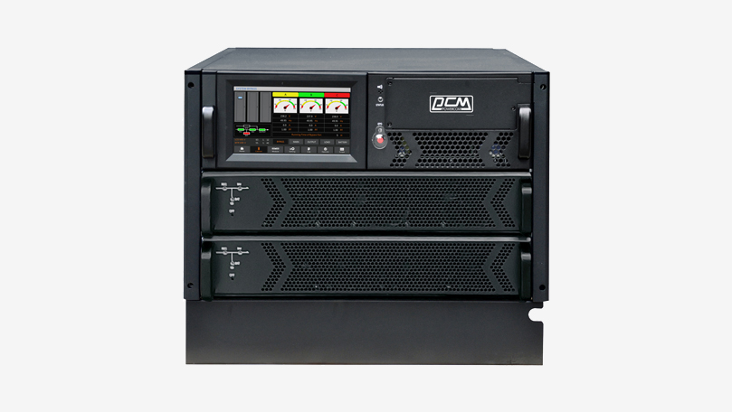
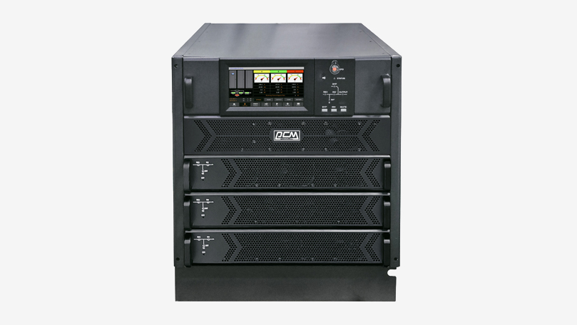
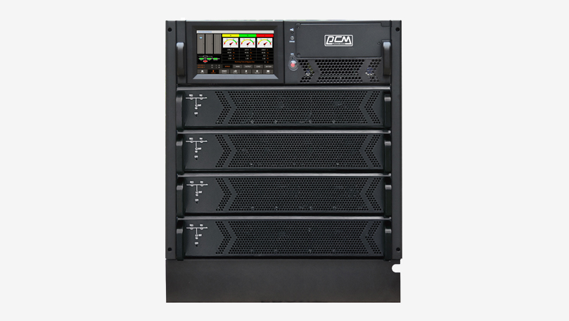
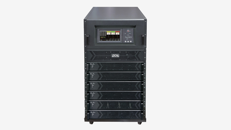
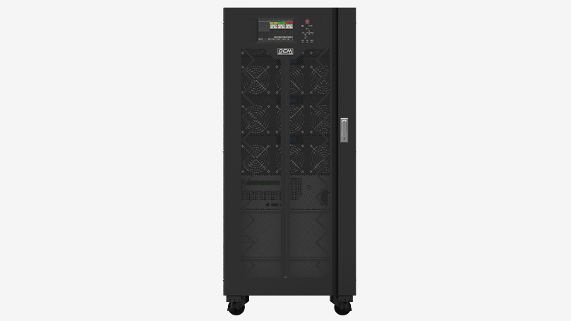
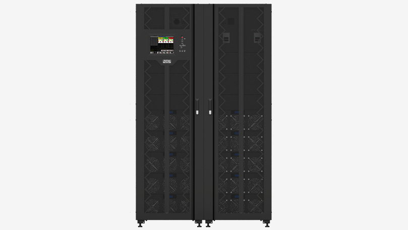
| POWERCOM VGDII Modular UPS provides Pure Sine Wave output for precision electronic equipment. The VGDII Modular UPS is designed to provide the safest protection for advanced Data Centers and Server Rooms. The VGDII - M with Double Conversion Topology brings higher quality output and performance. The VGDII - M LCD Display directly indicates information for a better user experience. POWERCOM VGDII Modular UPS combines high-tech design and good model performance, and is the best choice for advanced Data Centers and Server Rooms. |